In this blog, we will generate a triangle and square in runtime. We will generate a mesh to hold data for this shape.
What Are Meshes?
In Unity, a mesh is used to hold the data of 3D objects. The mesh contains data such as vertices, edges, tris (triangle), normals etc. A 3D object consists of multiple vertices connected with edges. A face is created by joining multiple vertices creating a polygon. For generating a mesh in Unity, all faces should be triangles. For generating 3D objects, multiple faces can be created.
Meshes in Unity
In Unity, mesh data is held by the MeshFilter component. The MeshRenderer component holds materials, lighting data and other types of information for rendering objects. Both components work together to display objects in a scene.
Also read: Magic Beams VFX using Blender and GIMP
Triangle Mesh
For generating a mesh, let's first create an empty GameObject in a scene and add MeshFilter and MeshRenderer components to it. Also, we will create a material and assign it to MeshRenderer . You can assign a texture to that material. I am assigning a number grid texture to this tutorial so that visualizing it will be easier.
To generate a triangle mesh, create a MonoBehaviour script and attach it to the created gameObject. We generate mesh at the start of a scene, so all generating processes will run inside the Start method.
Creating Vertices
A triangle consists of 3 vertices, so create an array consisting of 3 Vector3 parameters. It will contain the position of the vertices. The vertices index is important as it will be used to map vertices to UV, assign normals, and create triangles and other mesh data.
public MeshFilter meshFilter;

void Start() {
  Mesh mesh = new Mesh();

  // generate vertices
  Vector3[] vertices = new [] {
      // generating three vertices for triangle
      new Vector3(0, 0, 0),
      new Vector3(-1, 1, 0),
      new Vector3(1, 1, 0),
  };

  mesh.vertices = vertices;
}
Creating Vertices for Mesh
UV Mapping Vertices
UV mapping is done to map a face into a texture. A UV map gives the position of vertices in 2D space so that texture can be applied to objects correctly.
A UV map is a 2D space where the coordinate ranges from (0,0) to (1,1). Each created vertices should be mapped in the UV map. To create a UV map data, create a Vector2 array and add the position of vertices in it. The Vector2 should be in the order of vertices we created.
// generate uv
Vector2[] uv = new [] {
    // generated vertices will be mapped to corresponding coordinates in uv
    new Vector2(0.5 f, 0),
    new Vector2(0, 1),
    new Vector2(1, 1),
};
mesh.uv = uv;
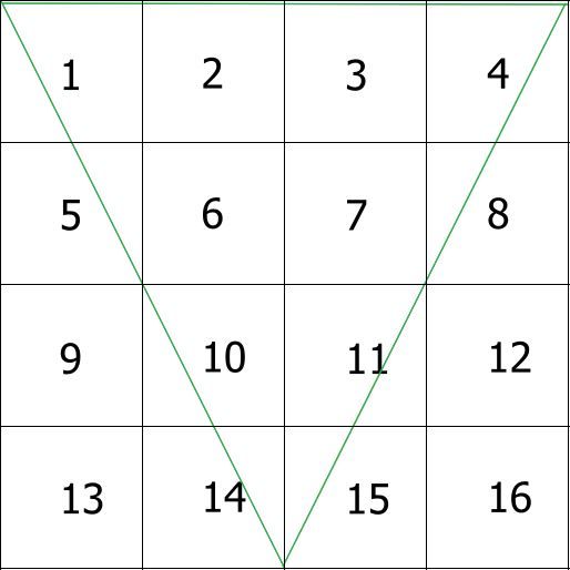
Mapping UV

The green line indicates the connected vertices mapped in the UV coordinate.
Pointing Normals for Vertices
Normals give the direction where a vertex is facing. It is useful when calculating lighting. Let's make a normal for all vertices perpendicular to the triangle we will be creating. Giving incorrect normals may produce weird lighting.
Vector3[] normals = new [] {
    // pointing normal at (0,0,-1) i.e perpendicular to triangle we will be creating
    // flipping normals gives incorrect lighting
    -Vector3.forward,
    -Vector3.forward,
    -Vector3.forward,
};
mesh.normals = normals;
Setting Normal for Each Vertex
Making Triangles
The last step is making triangles. A triangle can be created by joining three vertices. For this, create an array of integers. In this array, fill 3 numbers consisting of the indexes of the vertices we created earlier. Those vertices will be connected. This array should always be grouped into 3 values, giving the index of vertices to connect. To create the next triangle, add 3 indexes referencing vertices we created earlier.
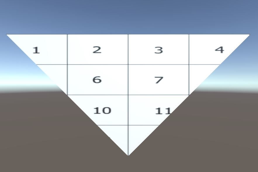
While creating a triangle, the order of vertices is important. They should always be ordered in the clockwise direction from where we are viewing. Otherwise, they will be rendered in the wrong direction.
int[] triangles = new [] {
  // vertices index should be in clockwise order.
  // if it is in anticlockwise order mesh will be invisible from that direction

  0,1,2// index of vertices for creating triangle
};
mesh.triangles = triangles;

meshFilter.mesh=mesh;// assign mesh to mesh filter after all setup are done
Creating Triangles

Related article: Using Unity's New Input System
Creating Quads
A quad consists of 4 vertices. In Unity, we cannot directly connect 4 vertices. So, we need to divide it into two separate triangles. Same as triangle generation, we need to create an array of vertices. Create 4 vertices forming a corner of a square.
The next step is to map them in the UV. Map the vertices of the 4 corners of square i.e (0,0), (0,1),(1,0),(1,1).
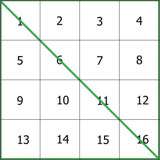
A mapped UV looks as follows. The green line in the following diagram marks edges creating triangles.

The generation of normal is the same as a triangle. We will be using the same value -Vector3.forward as a triangle for this.
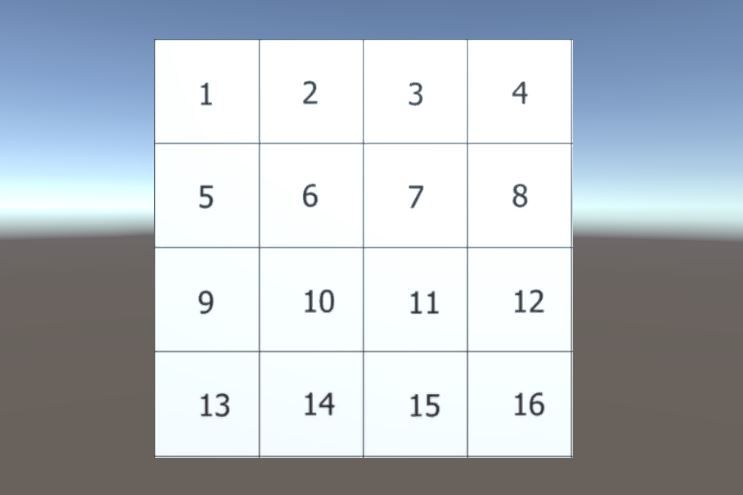
The next step is to generate triangles. We will need 2 triangles for a square. Another triangle can be created by adding a set of 3 integers. These indexes point to the index of the vertices to connect. Remember to order them in the clockwise direction; otherwise, they will be rendered incorrectly.
Vector3[] vertices = new [] {
    // creating vertices of quad. aligning them in shape of square

    new Vector3(0, 0, 0),
    new Vector3(0, 1, 0),
    new Vector3(1, 0, 0),
    new Vector3(1, 1, 0),
};
mesh.vertices = vertices;


// generate uv
Vector2[] uv = new [] {
    // generate uv for corresponding vertices also in form of square

    new Vector2(0, 0),
    new Vector2(0, 1),
    new Vector2(1, 0),
    new Vector2(1, 1),
};
mesh.uv = uv;

Vector3[] normals = new [] {
    // normals same as tris
    -Vector3.forward,
    -Vector3.forward,
    -Vector3.forward,
    -Vector3.forward,
};
mesh.normals = normals;

int[] triangles = new [] {
    // tris are viewed as group of three
    // remember to order them in clockwise
    // position of index is not importaint as long as they are in clockwise order

    0,1,2,// first tris
    2,1,3// second tris
};
mesh.triangles = triangles;
meshFilter.mesh = mesh;
Generating Quad

Conclusion
In this blog post, we have created 2 types of meshes. Although both objects are 2D planes, they exist in 3D space, so we can treat them as 3D objects. A cube can be made following the same process. A cube contains 8 vertices and 12 tris, 2 for every 6 faces. Normals can be assigned facing away from the cube's centre towards its vertices. UV position can be mapped as you want.
Generating meshes at runtime is useful for generating procedural terrain, animating vertices of a 3D object, combining multiple 3D objects in runtime etc. Manipulating meshes can produce lots of new possibilities for games. Although we have created simple objects, this concept can be used to create more complicated shapes, so feel free to explore more.
Thanks for reading, more blogs coming soon.
