
Today, we will be animating realistic gears using keyframe animation, animation constraints, drivers, and bones. We don't have to create and adjust animation data on multiple gears manually using this method. By the end of this process, we will be able to animate various kinds of gears as shown below.
Adding Gears
This article assumes you have intermediate knowledge of Blender.
First of all, enable the Add Mesh: Extra Objects add-on. We can now find the option to create a basic gear model under Add> Mesh > Gears . We can then modify the basic model to our liking. For simplicity, we will be using an even number of teeth on all our gears.
Animating Gears With the Same Number of Teeth
Create a gear and set your desired number of teeth. Duplicate the gear and position it so that the teeth align perfectly.
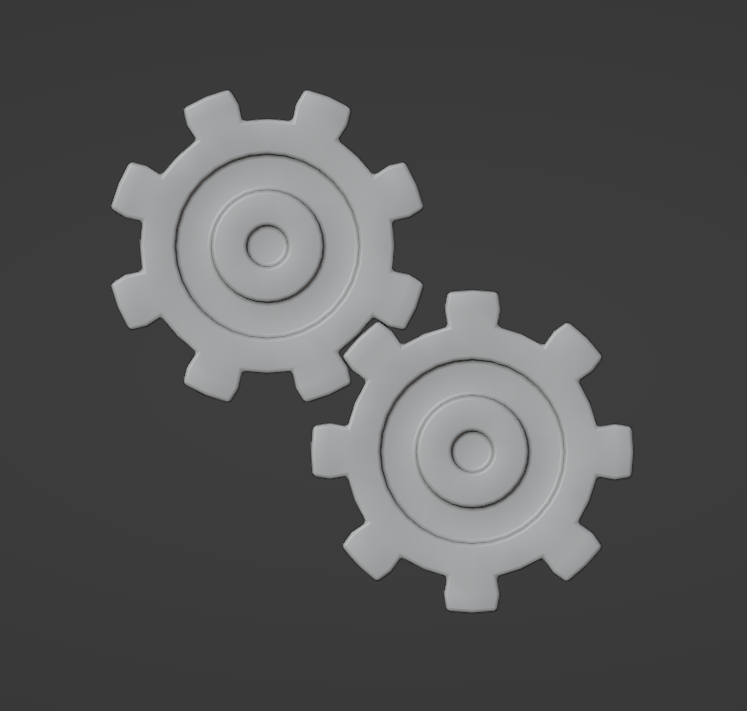
Now, animate the original gear rotation using keyframe animation (along the z-axis in my case). For the second gear, use the Copy Rotation constraint to do the same.
Here I inverted the rotation on the z-axis because the neighboring gear rotates in the opposite direction. I also set the Target and Owner mode to Local Space so that any rotation changes on other axes won't cause any issues.
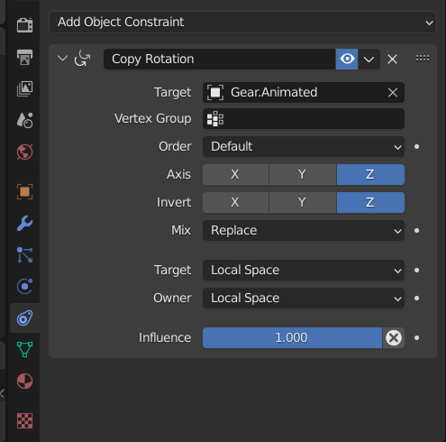
The first gear animation is now ready.
Animating Gears with Different Radii or Different Number of Teeth
We can't use simple rotation constraints for gears with different radii and/or the number of teeth. So, we will be using drivers instead.
While creating complex gear systems, gear radii and the number of teeth is very important.
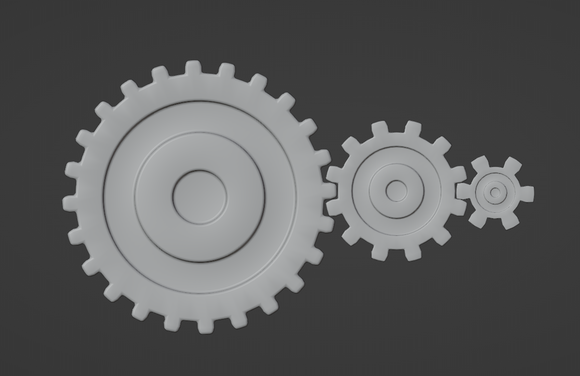
In my case, I first created a small gear with six teeth and a radius of 0.25m. Then, I created a medium gear with double the radius and teeth, i.e. 0.5m radius and 12 teeth. Finally, I added a big gear with double the radius and number of teeth of the medium gear, i.e. 1m radius and 24 teeth.
I chose these radii and teeth to simplify my calculation later on.
Animate the middle gear with the good old keyframe animation. We add drivers for the other two gears and animate them that way.
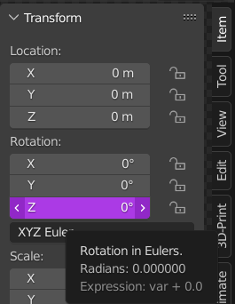
To add a driver select the object and hover over the transform value you want to add the driver to (z-rotation in my case). Press CTRL + D or Right Click > Add Driver.
As we have used gear of double and half the size of the animated gear, we can simply divide and multiply the z-rotation value by two. This makes the big gear rotate at half the speed and the small gear at double the speed of the mid gear.
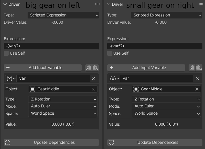
You can also use this figure as a reference and adjust the driver values. When done, just hit the Update Dependencies button, and your gears will animate.
Animating Gears Around Other Gears
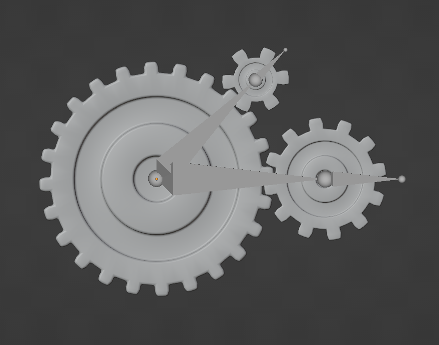
Now let's animate a gear around another one. This time we will be using bones and drivers together. We can start with a similar three-gear configuration as in the section above.
Arrange the gears as shown in the figure below. Add a bone from the origin of the centre gear to the origin of the small gear surrounding it. Extrude the bone to create a child bone. Parent the small surrounding gear to the child bone using pose mode. Repeat this process for all additional gears.
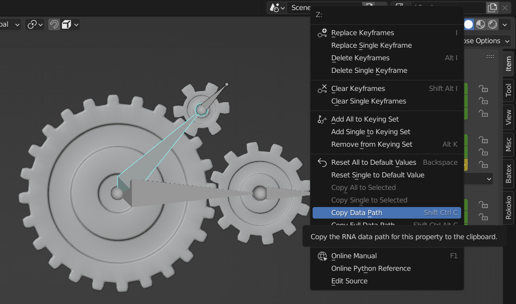
Now, select all bones in pose mode using Ctrl + R, and set the rotation mode to XYZ Euler. Then, animate the parent bone rotation using keyframes and copy the data path of the animated parent bone.
I copied the z-axis value, as it is the axis I animated my parent bone on.
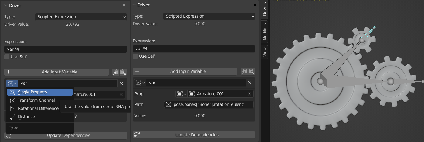
Now, to animate the child bone, add a driver to it. Set its type to Single Property. Paste the copied value in the Path option. pose.bones["Bone"].rotation_euler will be pasted.
As we need the z-axis value, add .z at the end. For the small gear bone, use var*4 and for the midsized gear bone use var*2. This value is obtained by dividing the centre gear teeth amount by surrounding gear teeth amount (24/6=4 and 24/12=2).
You will find that the surrounding gear will animate automatically now.
Using this method, gears with various radii and teeth can be easily animated realistically. As we are using math for animating neighboring gears, we don't have to worry about inaccurate animation. This process also makes it easy to animate complex gear configurations.
If you come across any difficulties make sure to leave a comment below!