
In Part 1, we created a Lens Distortion effect. In this part, we will add Chromatic Aberration to our Lens Distortion.
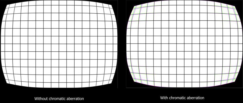
Chromatic Aberration is the splitting of light into multiple colours. We can get this effect at the corner and edges of a lens due to uneven thickness. It is noticeable in older analogue cameras, binoculars, etc. This effect can be achieved in software by slightly varying the distortion strength of red, green and blue channels separately.
Continuing from our previous part, let's move on to the next steps.
Distorting RGB channels Individually
Let's create three properties _LensDistortionOffset_R , _LensDistortionOffset_G, _LensDistortionOffset_B. They will be used to offset the distortion strength of each channel.
Now, we can calculate distorted uv for each channel as uvRed , uvGreen , uvBlue . These values will be calculated in the same way as the calculation of uvDistorted in Part 1. The only change is the addition of LensDistortionOffset to _lensDistortionOffset in each channel so that the channels vary from each other.
After getting the separated uv, we can get the pixel value at the uv position and set it as the pixel value of _finalColour on the corresponding channel.
Out of bound will be detected when the uv value of any channel lies outside of the 0-1 range. In this case, the pixel's value will be set to _OutOfBoundColour.
fixed4 frag(v2f i): SV_Target {
  ...

  // separate channels will be distorted so don't need to distort whole image
  // remove section to distort image.
  // float2 uvDistorted=i.uv+(uv_centered>0?1:-1)*smoothDistortionMagnitude*_LensDistortionStrength;
  //float2 uvDistorted=i.uv+uv_centered*smoothDistortionMagnitude*_LensDistortionStrength;
  // if(uvDistorted[0]<0||uvDistorted[0]>1||uvDistorted[1]<0||uvDistorted[1]>1)
  // {
  //     return _OutOfBoundColour;
  // }else
  // {
  //     return tex2D(_MainTex,uvDistorted);
  // }

  //distort red channel
  float2 uvRed = i.uv + uv_centered * smoothDistortionMagnitude * (_LensDistortionStrength + _LensDistortionOffset_R);
  //check for out of bound
  if (uvRed[0] < 0 || uvRed[0] > 1 || uvRed[1] < 0 || uvRed[1] > 1) {
    isOutOfBound = true;
  } else {
    finalColour[0] = tex2D(_MainTex, uvRed)[0];
  }

  //distort green channel
  float2 uvGreen = i.uv + uv_centered * smoothDistortionMagnitude * (_LensDistortionStrength + _LensDistortionOffset_G);
  if (uvGreen[0] < 0 || uvGreen[0] > 1 || uvGreen[1] < 0 || uvGreen[1] > 1) {
    isOutOfBound = true;
  } else {
    finalColour[1] = tex2D(_MainTex, uvGreen)[1];
  }

  // distort blue channel
  float2 uvBlue = i.uv + uv_centered * smoothDistortionMagnitude * (_LensDistortionStrength + _LensDistortionOffset_B);
  if (uvBlue[0] < 0 || uvBlue[0] > 1 || uvBlue[1] < 0 || uvBlue[1] > 1) {
    isOutOfBound = true;
  } else {
    finalColour[2] = tex2D(_MainTex, uvBlue)[2];
  }

  if (isOutOfBound) {
    return _OutOfBoundColour;
  }

  return fixed4(finalColour, 1);
}
(Optional) Adding Distortion to Textures Rendered by the Camera
If you are adding this distortion shader to the camera, you need to add post-processing to it as well. We will pass the image rendered by the camera to this shader.
Unity has OnRenderImage event function that gets called once image render is complete. It consists of source and destination as its parameters. The rendered image is obtained as the source. This source needs to be processed and set as a destination. The shader can be applied using Graphics.Blit() method.
A material is required to use this method, so create one with this shader. Also, add the ExecureInEditMode attribute in the beginning to apply the shader when the game is not running.
Finally, attach this script to the camera.
[ExecuteInEditMode]
public class CameraPostProcessing : MonoBehaviour
{
    public Material material; //this material will contain distortion shader
    private void OnRenderImage(RenderTexture src, RenderTexture dest)
    {
        Graphics.Blit(src,dest,material);//apply shader to rendered image
    }
}Further Modifications
- Set
RenderTypetag toTransparentif you want transparency. Doing this will allow the use of a transparent out of bounds colour, which will be quite useful when hiding extra space. - Calculating
distortionMagnitudeasdistortionMagnitude=sqrt(uv_centered[0]*uv_centered[0]+uv_centered[1]*uv_centered[1])in the first step in creating a Lens Distortion effect will generate a map in a circular pattern. This can be used to create distortion in circular lenses.
- Experiment with multiple types of equations for
smoothedDistortionMagnitude. They can produce interesting results by distorting images in different patterns. It can be used to make lenses of different cross-sections.
This shader can be used to make concave and convex lenses, mirrors, fish-eye views etc.
A demo of this effect is shown below.
So concludes our lengthy tutorial. Leave a comment if you faced any difficulties.