
Have you ever wondered why rendered images feel too straight or stiff compared to real pictures? Well, there might be two reasons for this.
Firstly, real-world images and videos have some distortion due to curved camera lenses. This results in straight lines along the edges of a photograph curving inwards or outwards. This effect is known as Lens Distortion.
Another common effect is Chromatic Aberration. In some older photographs, we can see that the light gets split into different colours, resulting in a rainbow-like effect at the corners.
These effects are common in many real-world cameras, binoculars, scopes, mirrors, etc. So today, we will learn how to create these effects in Unity using shaders.
In this part of this series, we will only be looking at Lens Distortion.
Lens Distortion Types
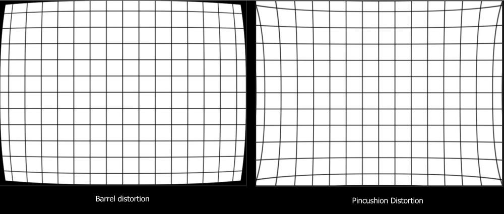
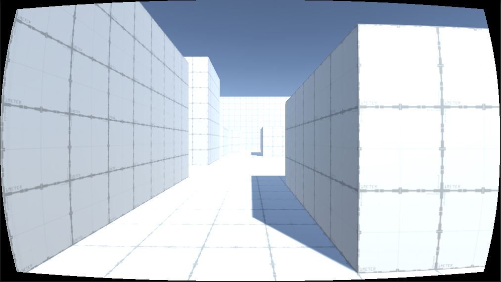
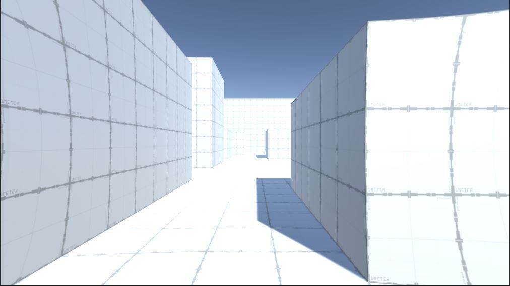
Lens distortion is usually classified into two types: Barrel Distortion and Pincushion Distortion. In barrel distortion, corners converse towards the centre of the image, while in pincushion distortion, they diverge away.
Today, we will learn how to create both types of distortion.
Creating Lens Distortion
Let's start by creating a shader and adding material for it. This shader can be applied to an image to distort it or the camera itself to distort everything the camera renders.
Let us first start by creating an unlit shader. We will be using an unlit shader because we don't want it to be affected by lighting.
Step 1: Remapping UV
fixed4 frag(v2f i): SV_Target {
  const float2 uvNormalized = i.uv * 2 - 1; //change UV range from (0,1) to (-1,1)
  const float distortionMagnitude=abs(uv_centered[0]*uv_centered[1]);//get value with 1 at corner and 0 at middle
  return distortionMagnitude;//preview distortionMagnitude
}In the shader we created, we have a frag function. This will be called once for every pixel in each frame. Each i of type v2f will be passed to it as a parameter. The i will then interact with the uv position of the current pixel.
The uv variable is a float2 variable that has values in the range of (0,1). We will now convert uv to uv_centered, so that the domain for the values increase to (-1,1). We set(0,0) as the centre point and 1 as the corner of uv_centered. This change will give us the direction of distortion.
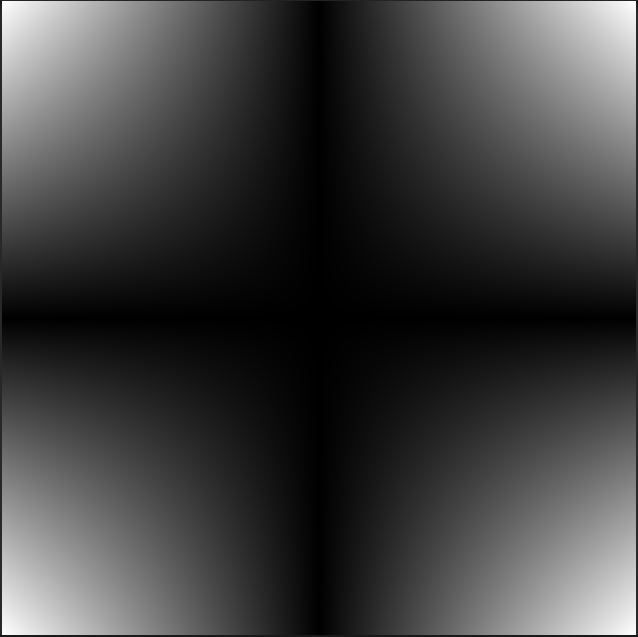
After remapping uv, we need to get distortionMagnitude. This is the magnitude of distortion applied at any uv position. On a real picture, we can notice that there is no distortion at the centre of the image, and the distortion gradually increases as we get closer to a corner.
To achieve this effect, we need to multiply x and y components of uv_centered. The closer we get to the centre, the lower our multiplication number. This makes it so that the centre has a 0 and the corners have a 1 multiplication factor.
Also, we use abstract values as we only need the magnitude, and direction is not important.
Step 2: Smoothing Distortion Map
We can't use this map yet because the change in magnitude is linear. Using it will create a distortion effect with a straight line broken at the centre.
To make it smooth, lets pass distortedMagnitude through the exponential function x=by .
float _LensDistortionTightness;

fixed4 frag(v2f i): SV_Target {
  ...

  const float smoothDistortionMagnitude = pow(distortionMagnitude, _LensDistortionTightness);//use exponential function
  // const float smoothDistortionMagnitude=1-sqrt(1-pow(distortionMagnitude,_LensDistortionTightness));//use circular function
  // const float smoothDistortionMagnitude=pow(sin(UNITY_HALF_PI*distortionMagnitude),_LensDistortionTightness);// use sinusoidal function
  return distortionFunction;// previewing smooth distortion map
} Here,
x = smoothed value. Let's call it smoothDistortionMagnitude
b = distortedMagnitude
y = exponent of function. This determines the tightness of the curve. Let us declare it as _LensDistortionStrength. We will expose this as a 'property' to modify it from the editor when desired.
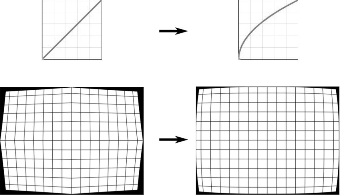
We could also use other functions such as y=sin(πb/2)x or y=1-sqrt(1-bx) . Using these will yield different types of curvature.
Step 3: Distorting Original UV
Now, since we have the distortion magnitude, we just need to distort the original i.uv with this magnitude. This distortion vector is obtained by multiplying uv_centered with distortionMagnitude .
float _LensDistortionStrength;
float4 _OutOfBoundColour;

fixed4 frag(v2f i): SV_Target {
  ...

  float2 uvDistorted = i.uv + uv_centered * smoothDistortionMagnitude * _LensDistortionStrength; //vector of distortion and add it to original uv

  //Handle out of bound uv
  if (uvDistorted[0] < 0 || uvDistorted[0] > 1 || uvDistorted[1] < 0 || uvDistorted[1] > 1) {
    return _OutOfBoundColour;//uv out of bound so display out of bound color
  } else {
    return tex2D(_MainTex, uvDistorted);
  }
}To get more control over distortion strength, let's multiply it by _LensDistortionStrength which we will expose as a 'property'. Setting _LensDistortionStrength to a positive value will create a barrel distortion, and setting it to a negative value will make a pincushion distortion.
We have,uvDistorted=i.uv+uv_centered*smoothDistortionMagnitude*_LensDistortionStrength
When uvDistorted is out of bound, i.e., when it is not in between 0 and 1, some artefacts can be created. So to avoid those, let's add some colour to those spaces. The colour added will be exposed as a 'property' so that it can be modified from the editor.
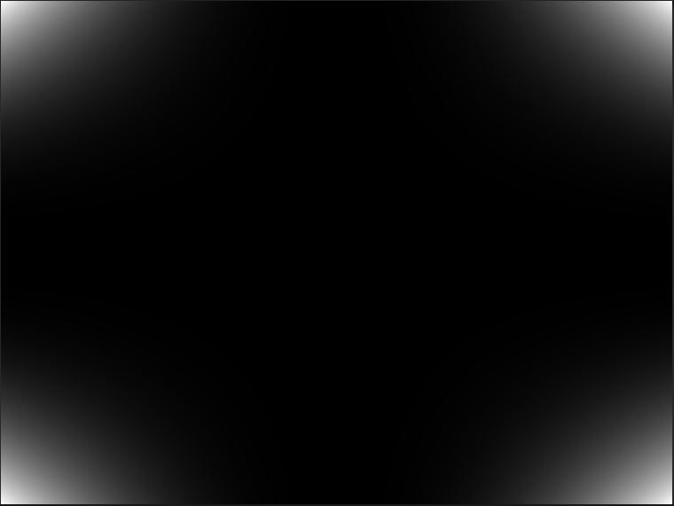
Step 4: Using the Shader
Our shader is now ready for use. We simply create a material, link this shader to it, and use this material per our needs.
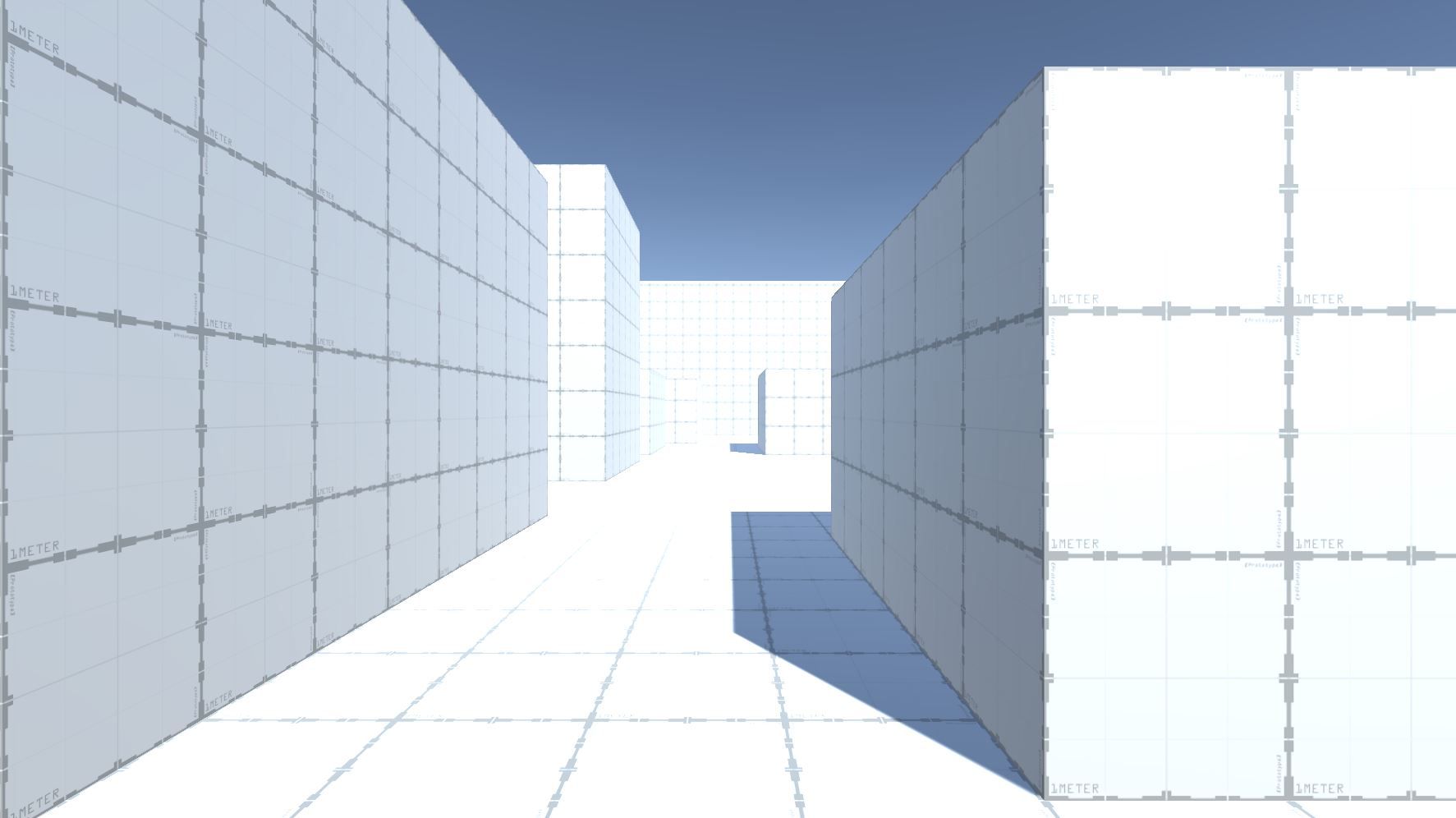
To use it in an image, we can simply drag and drop this material to the material property of the image. The same can also be done to the camera to show the effect everywhere while playing the game. Examples of this effect in-game are shown below.
We will use this material with a camera and create the Chromatic Aberration effect in part 2. Stay tuned! Edit: Part 2 is here!