
What is a Shader?
All objects in games, such as 3D objects, 2D UI elements, and sprites, are rendered into a single image before displaying on the screen. Shader takes object data from GameObject of the scene and processes it so that it can be shown on a 2D screen.
These object data may vary from different object types. For example, a 3D object consists of vertices, information about its transform (position, rotation, scale), and UV information. A 2D sprite contains colour information and depth value. The Shader's job is to take those data and process them so they can be shown on screen.
Most of the time, Shader programs run on video hardware (graphics card). It means it can execute multiple parallel processes at a time. It is also faster than running on a CPU.
Step 1: Creating a Material
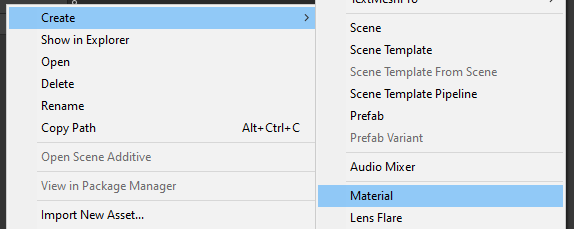
To create a Shader, create a material. A material can be created by clicking right on an asset and selecting Create > Material. You can name it to MaterialExample.
Step 2: Creating the Shader
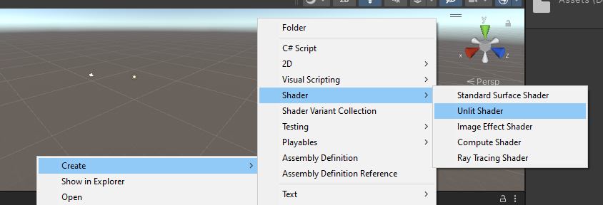
Then create a Shader. For this tutorial, we will be creating an unlit shader. Lighting will not affect this Shader, so it will be easier to demonstrate its usage. It can be created using Create > Shader > Unlit Shader. Rename it to ShaderExample.
You can find this Shader in Unlit/ShaderExample. But it is a good idea to create a custom path for custom Shaders.
Step 3: Creating a Custom Path
To give a custom path, open the Shader file in IDE. You can find the first line, Shader "Unlit/ShaderExample". Edit this to give a custom path as Shader "[PATH_TO_SHADER]". I have changed the path to "Custom Shader/ShaderExample".
Step 4: Assigning the Shader
Now assign the shader to the created material. To do that, select material in the asset window and shader in the inspector window. At the top, we can see default material is being used. Click on it and select Custom Shader > ShaderExample. This material will now use a new shader.
This material can be assigned to any 3D object. To see this material in action, create a plane at position 0,0,0 and drag-drop material to it. This plane will now use our custom shader.
All required steps are complete, and we are ready to work on the shader.
Vertex Shader
A vertex shader is used to manipulate the vertices of an object. All 3D objects are made up of vertices. We can use this to manipulate each of the vertices. Vertex can be manipulated using the vert method of the shader. This method will be called once for each vertex of an object. Struct of type appdata is passed to this method consisting of information about the vertex which consists of vertex and UV giving the position of the vertex in the UV map.
A UV map is a 2D plane where all vertices of an object are mapped. The value of UV ranges from 0 to 1. UV of appdata consists of the coordinates of vertices in the UV map. Definition of appdata structure can be found in the same script. This method expects v2f value to be returned that has a similar structure as appdata, consisting of vertex and uv. The idea is to get the UV and position of the vertex, manipulate it, and return the manipulated value.
Transforming the Position
Let's start with a simple task. We will transform the position of all vertices of an object by 1 on the y-axis.
v2f vert(appdata v) {
  v2f o;
  o.vertex = UnityObjectToClipPos(v.vertex);
  o.uv = TRANSFORM_TEX(v.uv, _MainTex);
  UNITY_TRANSFER_FOG(o, o.vertex);

  // start manipulation
  o.vertex.y += v.vertex.y + 1; // transform vertices along y axis by 1
  return o;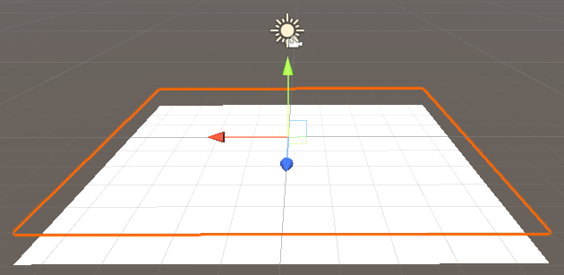
}Give attention to the line o.vertex.y+=v.vertex.y+1; and ignore other lines as they are auto-generated. In that line, we have increased the y value of the vertices by 1. You can see the result in the Unity editor when selecting the plane. The selected plane's graphics are moved by 1 unit even when the transform is at the origin.
Let's make it more interesting. Instead of transforming all vertices by 1, transform vertices using the sine() function. Using x position of vertices, get the transform value of vertices.
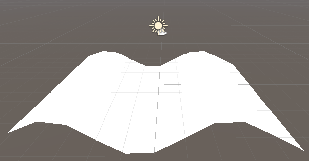
Replace the above line as o.vertex.y+=sin(v.vertex.x);. You can notice the plane is now distorted as a sine wave. Here, we passed the x position of vertices as input for the sine function. That means the x value will be different for vertices resulting in sine distortion.
Using Time Function
You can even animate it using the time function. _Time is a float 4 that gives the time that keeps on increasing over time. It consists of (t/2,t,t*2,t*3) in it, where t increases by 1 second.
To animate it, make small modifications to the above code, o.vertex.y+=sin(_Time[3]+v.vertex.x);. I have used _Time[3] but any available value can be used to control the speed of animation.
Here, we are passing x position of vertices and adding time to it. As time increases constantly, sine outputs oscillating values that results in following animation.
sine() FunctionSo far, we have discussed the shader and how it can be used to manipulate the vertices of an object. In the next part, we will discuss fragment shader and how it can be used to manipulate each pixel that will be rendered.
This project with all used scripts and assets can be found on my Github. Have fun tinkering with it.
Thanks for reading, part 2 will be published soon. Comments are welcome.